
This TechLetter aims at presenting in a simple and didactic way the complex topic of functional safety assessment and its application to batteries. This topic is covered by several standards, most of which are derived from ISO 61508. We will here focus on 2 standards:
- ISO 13849, which goal is to ensure critical safety functions for machineries.
- ISO 26262, which goal is to ensure safety for electronics functions in road vehicles;
We will see their common points and differences, and explore an implementation of ISO 26262 in the case of WATTALPS batteries.
ISO 26262 process vs ISO 13849
When WATTALPS tried to sum-up the differences between ISO 26262 and ISO 13849 processes, we could not find a better explanation than the one given by Michael Kieviet from CAN Automation, who we therefore quote here:
“If components will be used for passenger vehicles and in machineries, a common understanding about main differences in the standards must exist. In fact the ISO26262 includes ten parts with nearly 400 pages in sum. In comparison the ISO13849 which has just two parts with around 200 pages and a lot of references to IEC61508 with seven parts and additional 700 pages. This will give just a subjective imagine about the effort. The main difference is the philosophy behind the standards. The safety function in machinery is usually an additional functionality which does not controls the process. That means, if the safety components will be removed, the machinery will still work. This implies additional components and of course additional costs for getting a safe system. The ISO26262 has the intention to provide the functional component as an intrinsic safe device. This should reduce the part costs, but increase the development costs.”
WATTALPS chose to develop its electronics according to ISO 26262 to provide a maximum safety level combined with a reasonable cost for its customers.
Risk analysis
Both standards start with a risk analysis. This risk analysis is depending on the application:
- Are there people around the battery?
- Are these people protected by any other mean from a battery incident?
- Is there anyway for these people to avoid being hurt in case of a battery incident (easy/difficult evacuation, additional passive protection, etc)?
The risk analysis is performed without taking into account the safety mechanisms added to protect people. It permits to get a gross assessment of the actual risk if no care is taken for the functional safety of the system.
This risk assessment permits to set target reliability levels for the associated safety functions. The table here below presents the different reliability levels for a lot of standards on functional safety. It also approximates equivalence of safety levels between standards (e.g. ISO 13849 PL e is close to ISO 26262 ASIL-D).
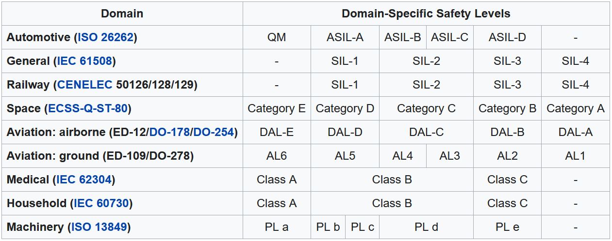
Source : https://en.wikipedia.org/wiki/Automotive_Safety_Integrity_Level
For both ISO26262 and ISO 13849 standards the risks are assessed using 3 criteria:
- Exposure : representing the time during which people are exposed to the risk when the battery is used (i.e. charged, or discharged)
- Severity: representing the consequences of a dangerous failure of the battery system
- Controllability: representing the likelihood to limit or avoid the consequences of the dangerous failure (evacuate, drive in a safe place…)
An event with a high exposure, a high severity and a low controllability will result in an assessment of ASIL-D according to ISO 26262 and PL-e according to ISO 13849. On the contrary, a low exposure, low severity and high controllability will result in a risk assessment of PL-A according to ISO 13849 and no ASIL level according to ISO26262.
Reliability parameters
Once the risk has been assessed for each dangerous event, a reliability goal is set for each safety goal. A partial example for an excavator battery in an outdoor construction site with ISO 26262 is given here below:
| Safety goal | Undesired event | ASIL level |
| Fire | Fire due to overvoltage due to wrong cell voltage measurement | B |
| Fire due to overtemperature due to wrong cell temperature measurement | B | |
| Fire due to overcurrent due to wrong current measurement | B |
Each function developed to protect from the unexpected events listed here above will then have to respect metrics of reliability established by the norm as a function of the risk assessment (ASIL or PL levels).
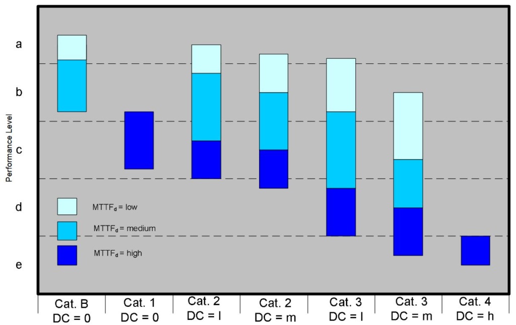
For ISO 13849, these metrics are:
- MTTFd : Mean Time To dangerous Failure (see failure rate table here below)
- DC: Diagnostic Coverage, reflects the capacity of the system to detect dangerous failures.
- Categories: the architecture of the system can be imposed depending on the targeted PL level and the metrics of MTTFd and DC (see graph below).
- For ISO 26262, no architecture is imposed but additional metrics are used to check that the reliability of the whole system is at the desired level:

- SPFM : Single Point Fault Metric, evaluates the robustness of an item to single fault by design or by coverage from a safety mechanism.
- LFM : Latent Fault Metric, evaluates the robustness of an item against a latent fault (fault not visible until the unexpected event occurs).
- PMHF : Probabilistic Metric for random Hardware Failures, evaluates the residual risk of a safety goal violation (see failure rate table here below)
| ISO 26262 | Failure rate (PMHF) | ISO 13849 | Failure rate (MTTFd) |
| PL a | <10-4/h | ||
| PL b | <10-5/h | ||
| PL c | <3×10⁻⁵/h | ||
| ASIL A | (<10-6/h) | PL d | <10-6/h |
| ASIL B, C | <10-7/h | PL e | <10-7/h |
| ASIL D | <10-8/h |
WATTALPS ISO 26262 ASIL B/C BMS development
WATTALPS Battery Management System is composed of the following functionalities:
- Battery Safety Management (BSM)
- Battery Modularity Management (BMM)
- Battery Interface Management (BIM)
- Battery Thermal Management (BTM)
- Battery Connectivity Management (BCM).
The Battery Safety Management (BSM) has been developed following the requirements of ISO 26262 ASIL C for functional safety.
The battery system is seen as a “System Out Of Context” so as to be integrated in different possible applications. The WATTALPS BSM includes the capacity to open the main battery contactors to put the battery in a safe state. To keep the battery in a safe operating zone, the following components are included in the BSM:
- Slave board and connection to battery module
- Master board, software and communication to slave board
- Junction box
- Battery heating management
- Dielectric fluid level detection
- Interface with application in case of a fault detection.
You will find here under an extract of the metrics of WATTALPS BSM assessed by a specialized company who partnered with WATTALPS for this topic.
| Undesirable event | SPFM* | LFM* | PMHF* | Achievable ASIL* |
| Fire due to overvoltage due to wrong cell voltage measurement | 99,64% | 98,13% | 7,25×10⁻⁹ | D |
| Fire due to overtemperature due to wrong cell temperature measurement | 99,23% | 97,99% | 6,06×10⁻⁹ | D |
| Fire due to overcurrent due to wrong current measurement | 98,15% | 96,78% | 2,42×10⁻⁸ | C |
* These metrics are valid for a given configuration and mission profile and could vary upon application.
All safety functions of the WATTALPS batteries have been assessed, designed and validated for a maximum application voltage of 800V. Apart from its BSM, WATTALPS has put safety at the heart of its development with:
- Top quality and top safety cells from the best suppliers
- No risk of short circuit due to liquid cooling leakage
- Non propagation of thermal runaway at module and battery level
- IP67 robust casing designed for rough environment (shock, vibration, dust, salt spray, moisture…)
- Highly validated and tested products;
If you want to further study the topic of electronic functional safety, you can check out these documents from Cadence or from TI.


